What Are All the Continuity Equations
17 Conservation of Mass: Continuity Equation
Introduction
Having laid down the fundamental forms of the flow models used in aerodynamic analyses, the governing equations used to describe aerodynamic flows can now be formulated. The approach uses the three physical conservation principles, i.e.,
- Mass is conserved, i.e., mass is neither created nor destroyed but can be conveyed from one point to another.
- Momentum is conserved, which assumes the validity of Newton's second law, i.e., Force = time rate of change of momentum.
- Energy is conserved, i.e., applying the first law of thermodynamics.
Using these principles, a suitable mathematical model to describe the behavior of a fluid flow can be determined, which inevitably means the imposition of appropriate assumptions and/or approximations applicable to each problem. As previously explained, there are two modeling approaches traditionally used in aerodynamics:
- The finite control volume approach, which is sometimes called the integral approach because it deals with finite fluid volumes in space rather than individual fluid elements.
- The differential or infinitesimally small fluid element approach, which has the advantage of allowing the fluid properties at a point to be evaluated.
In each case, there are two approaches: 1. The Eulerian approach where the control volume or fluid element is fixed in space and the flow moves through it; 2. The Lagrangian approach where the control volume or fluid element moves with the flow. Each of these approaches has certain advantages and disadvantages when applied to a specific fluids problem, and part of engineering problem solving is to decide on what is the best approach to use.
To introduce the conservation laws of fluid dynamics, it is convenient to focus on the integral models, which are useful in that they can be used to relate the total properties of the fluid, i.e., what fluid properties are coming into the control volume versus what changes are coming out. However, in many other practical problems in which fluid properties at a point in the flow, it is usually necessary to use the differential (fluid element) model and apply this modeling approach to problem-solving.
- Understand the concepts of mass flux and mass flow.
- Know how to derive the most general form of the continuity equation in its integral form.
- Be able to use the continuity equation to solve some simple flow problems.
Mass Flow and Mass Flux
Before deriving the fundamental equations used in fluid dynamic or aerodynamic analysis, it is first necessary to examine a concept vital to all of these equations, which is the concept of mass flow. Consider a small, fully-permeable surface of differential area ![]() that is oriented at some angle in a flow, as shown the in the figure below.
that is oriented at some angle in a flow, as shown the in the figure below.
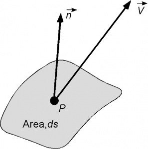
 of a control surface involves the calculation of the flow velocity normal to the surface times the area and density of the flow.
Let the area ![]() be small enough so that the velocity of the flow is constant across
be small enough so that the velocity of the flow is constant across ![]() , i.e., in the spirit of the differential calculus. Consider the orientation of the small surface to be defined in terms of a unit normal vector
, i.e., in the spirit of the differential calculus. Consider the orientation of the small surface to be defined in terms of a unit normal vector ![]() . The unit normal vector
. The unit normal vector ![]() defines the orientation of the surface where
defines the orientation of the surface where ![]() in perpendicular to the curvature of the surface and points away from the surface.
in perpendicular to the curvature of the surface and points away from the surface.
The mass flow ![]() through the surface
through the surface ![]() per unit time (the mass flow rate) will be given by
per unit time (the mass flow rate) will be given by
(1) ![]()
where ![]() is the magnitude of the velocity of the flow normal to the surface. Remember that is
is the magnitude of the velocity of the flow normal to the surface. Remember that is ![]() is the velocity of the flow through the surface, then the component of flow velocity normal (perpendicular) to the surface is given by by the dot-product
is the velocity of the flow through the surface, then the component of flow velocity normal (perpendicular) to the surface is given by by the dot-product
(2) ![]()
Mass flow rate has dimensions of (M L![]() ) (L T
) (L T![]() ) (L
) (L![]() ) = M T
) = M T![]() and so the units will be kg s
and so the units will be kg s![]() in SI or slugs s
in SI or slugs s![]() in USC.
in USC.
The mass flux is defined as
(3) ![]()
which has has dimensions of (M L![]() ) (L T
) (L T![]() ) = M T
) = M T ![]() L
L![]() and so units of kg s
and so units of kg s![]() m
m![]() or slugs s
or slugs s![]() ft
ft![]() . The mass flux terms like
. The mass flux terms like ![]() etc., occur frequently in fluid dynamic problem solving, so the meaning of these terms should be understood. The resulting mass flow then would be
etc., occur frequently in fluid dynamic problem solving, so the meaning of these terms should be understood. The resulting mass flow then would be
(4) ![]()
where ![]() is known as the unit normal vector area. These concepts of mass flux and unit normal vector area are used in the derivation of the governing equations for fluid dynamics and aerodynamic flows.
is known as the unit normal vector area. These concepts of mass flux and unit normal vector area are used in the derivation of the governing equations for fluid dynamics and aerodynamic flows.
Finite Control Volume Approach
In the finite control volume approach, a closed surface is drawn to contain a certain volume of the flow, as shown in the figure below. Obviously, this control surface (or control volume) needs to be large enough to contain the problem domain in totality. In some cases, the needed control volumes may be required to cover only part of the domain if certain flow conditions are known or defined elsewhere, which is not uncommon in practice. In fact, one of the problem-solving techniques that engineers must develop is to understand how to define the most suitable control surface/volume such that the governing equations can be applied and correct solutions for the flow properties so obtained.

The symbol ![]() is used to define the area of the closed surface that bounds the control volume containing a fluid of volume
is used to define the area of the closed surface that bounds the control volume containing a fluid of volume ![]() . The control volume is abbreviated to "C.V." and the control surface to "C.S.".
. The control volume is abbreviated to "C.V." and the control surface to "C.S.".
Notice: Be cautious not confuse the symbol for velocity (a vector ![]() or
or ![]() with the symbol for volume
with the symbol for volume ![]() or a "curly V." Sometimes the symbol
or a "curly V." Sometimes the symbol ![]() is used rather than
is used rather than ![]() but the meaning (volume) is the same.
but the meaning (volume) is the same.
As previously described, ![]() is a small elemental area of this surface and the vector
is a small elemental area of this surface and the vector ![]() is the unit normal vector. Because the product
is the unit normal vector. Because the product ![]() appears in the resulting equations for the flow, the unit normal vector area is defined as
appears in the resulting equations for the flow, the unit normal vector area is defined as ![]() . Remember that by convention
. Remember that by convention ![]() , and so also
, and so also ![]() , always points outward from the control volume in a direction that is perpendicular to the control surface. For example, if the surface is oriented perpendicular to the flow in the
, always points outward from the control volume in a direction that is perpendicular to the control surface. For example, if the surface is oriented perpendicular to the flow in the ![]() direction (i.e., in the
direction (i.e., in the ![]() –
–![]() plane) then
plane) then ![]() and if the surface is oriented perpendicular to the
and if the surface is oriented perpendicular to the ![]() direction (i.e., in the
direction (i.e., in the ![]() –
–![]() plane) then
plane) then ![]() .
.
Finally, as has been previously discussed, the control volume may either be fixed in space with the fluid moving through it (the most common application), which is called an Eulerian description of the flow, or it can move with the fluid such that the same fluid particles are inside it, which is called a Lagrangian model. In either case, the physical conservation principles must be applied to the fluid inside the control volume and to any fluid that crosses over its boundaries.
The applicable physical principle, in this case, is that mass can neither be created nor destroyed. This is a simple concept in principle, but perhaps initially appearing more challenging in application to an aerodynamic flow. Consider a flow field in which all properties are allowed to vary with spatial location (i.e., with respect to ![]() ,
, ![]() , and
, and ![]() ) and also possibly in time
) and also possibly in time ![]() so that
so that
(5) ![]()
Consider a fixed finite control volume ![]() bounded by a surface of area
bounded by a surface of area ![]() , as previously described. At any point on the control surface, the velocity is
, as previously described. At any point on the control surface, the velocity is ![]() , which is given in terms of the Cartesian components as
, which is given in terms of the Cartesian components as
(6) ![]()
At the same point the unit normal area is ![]() . Also, let
. Also, let ![]() be an elemental volume inside the control volume.
be an elemental volume inside the control volume.
The fundamental principle of the conservation of mass requires that the net mass flow out of the control volume over surface ![]() is equal to the time rate of decrease of mass inside the control volume
is equal to the time rate of decrease of mass inside the control volume ![]() . Now that physical statement must be translated into mathematics.
. Now that physical statement must be translated into mathematics.
Following the concept of mass flow and mass flux discussed previously, then the elemental mass flow across area ![]() is
is ![]() . Remember that by convention
. Remember that by convention ![]() always points out of the control volume, so the value of
always points out of the control volume, so the value of ![]() will be positive. Therefore, the total mass flow rate (i.e., the integral of the mass flow rate over the total surface area) is
will be positive. Therefore, the total mass flow rate (i.e., the integral of the mass flow rate over the total surface area) is
(7) ![]()
which can be physically interpreted as a net outflow that is leaving the control volume. Notice that the double integral here means the summation over the surface ![]() , i.e., an area integral.
, i.e., an area integral.
The small mass of fluid contained within the elemental volume inside the C.V. is ![]() . Hence, the total mass inside the C.V. is
. Hence, the total mass inside the C.V. is
(8) ![]()
where the triple integral here means a volume integral. So the time rate of decrease of mass inside the C.V. is
(9) ![]()
noting that the minus sign represents the decrease of mass, i.e., what is leaving the C.V.
Because the principle of conservation of mass requires that the net mass flow out of the control volume be zero, then Eq. 7 must equal Eq. 9, i.e.,
(10) 
or
(11) 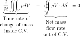
This latter equation is called the continuity equation for a fluid dynamic flow, in this case in the integral form. It is a very general equation valid for three-dimensional, unsteady flows and applies of all types of flows, e.g., compressible or incompressible, viscous or inviscid. It can be used to relate aerodynamic phenomena over a finite region of the flow, e.g., the properties of the flow as it comes into and leaves the specified control volume. The unknowns in the equation may include the flow velocities and the density of the flow.
Simplifications of the Continuity Equation
Various reductions or simplifications of the continuity equation can be used to solve practical problems, these forms also allowing commensurate simplifications in the overall mathematics. For example, for a steady flow, then nothing changes with respect to time and ![]() . This means that the continuity equation reduces to
. This means that the continuity equation reduces to
(12) ![]()
In words, the mass flow that comes into the control volume per unit time then leaves the control volume in the same time, i.e., no mass accumulates inside the control volume. The elimination of time-dependencies in aerodynamic problems, if this assumption can be justified, is a significant and worthwhile simplification in most forms of practical analysis.
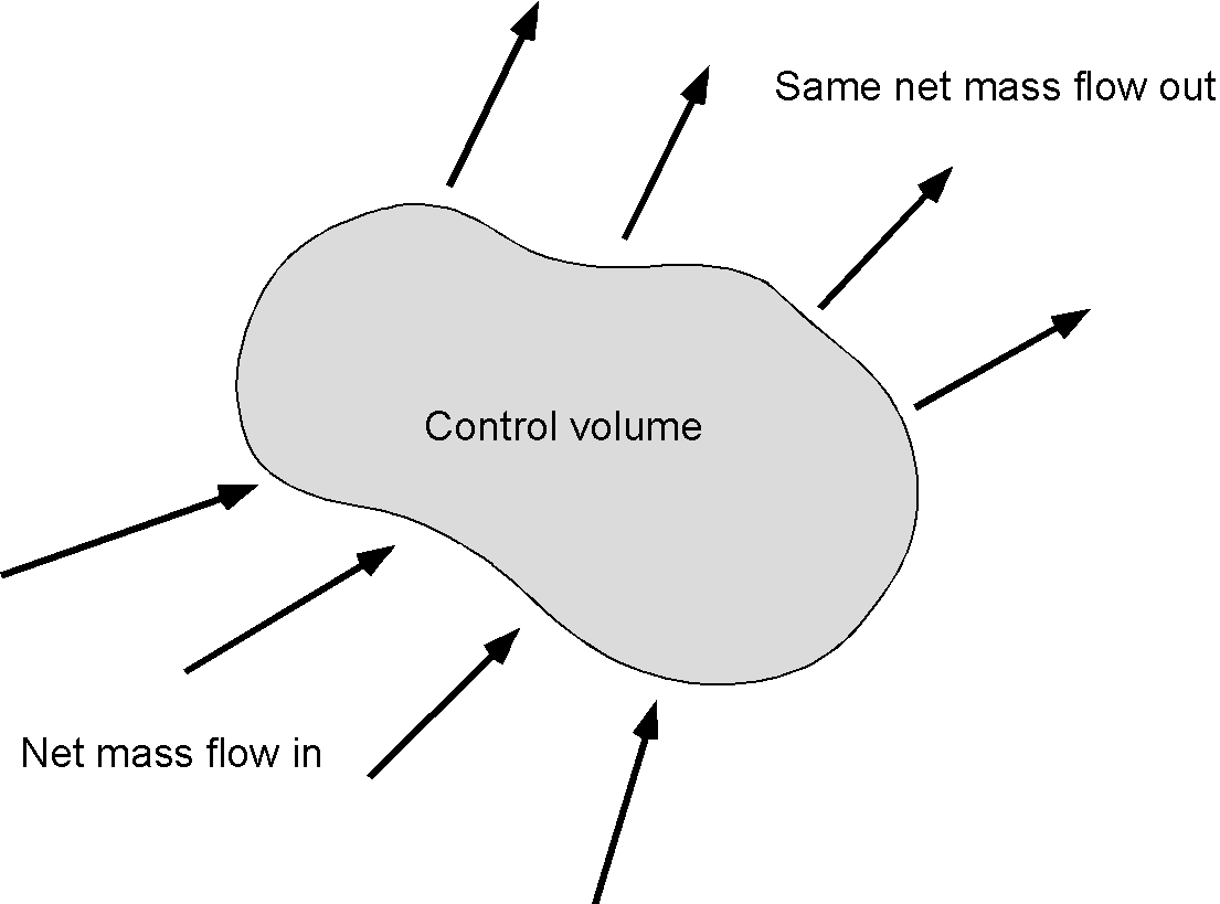
Proceeding further by assuming that the flow is both steady (![]() ) and incompressible (
) and incompressible (![]() = constant), then in this case, the governing continuity equation becomes
= constant), then in this case, the governing continuity equation becomes
(13) ![]()
which leads to a further significant reduction in the complexity of the governing equation, i.e., the elimination of ![]() as an unknown so that only the flow velocities need to be related.
as an unknown so that only the flow velocities need to be related.
Finally, consider a reduction to a steady, but compressible, one-dimensional flow in the ![]() direction, e.g., a uniformly axisymmetric flow. In this case
direction, e.g., a uniformly axisymmetric flow. In this case ![]() and so
and so
(14) ![]()
or
(15) ![]()
noting that the original surface integral now becomes a length ![]() or an area per unit depth. A much easier way to express this latter one-dimensional result is that
or an area per unit depth. A much easier way to express this latter one-dimensional result is that
(16) ![]()
or that the net algebraic sum of the mass flow inputs and outputs to the control volume is zero.
Consider the steady, uniform flow of air through a converging/diverging duct with a circular cross-section with inlet area ![]() and outlet area
and outlet area ![]() , as shown in the figure below. The two areas are known, such as by measurement. If the flow is assumed to be both steady and uniformly axisymmetric, then determine the relevant form of the continuity equation to relate the flow conditions at the outlet to those at the inlet.
, as shown in the figure below. The two areas are known, such as by measurement. If the flow is assumed to be both steady and uniformly axisymmetric, then determine the relevant form of the continuity equation to relate the flow conditions at the outlet to those at the inlet.
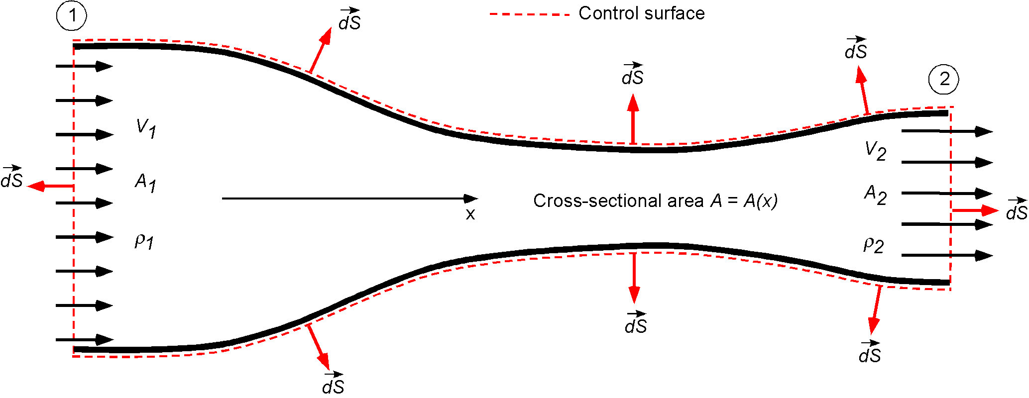
The first step in the solution is to define a coordinate system and the control surface/volume over which to apply the principle of conservation of mass. In this case, the decision on the control volume is fairly easy as the duct itself bounds the flow, and there can be no mass flow over the walls of the duct, and this naturally applies no matter what the shape of the duct is.
The flow is steady, so ![]() and no further justification is needed in this case. However, nothing is mentioned about whether the flow is compressible or incompressible. Because air is a gas, it must be assumed that the flow is compressible and that density must be retained as a variable. If the flow is uniformly axisymmetric, then the flow velocity changes only in one direction, i.e., in the
and no further justification is needed in this case. However, nothing is mentioned about whether the flow is compressible or incompressible. Because air is a gas, it must be assumed that the flow is compressible and that density must be retained as a variable. If the flow is uniformly axisymmetric, then the flow velocity changes only in one direction, i.e., in the ![]() direction based on the adopted coordinate system, another significant simplification toward the solution of this problem.
direction based on the adopted coordinate system, another significant simplification toward the solution of this problem.
In light of the foregoing assumptions, therefore, in this case then
![]()
where the latter term is zero because there is no mass flow over the walls, i.e.,
![]()
The mass flow coming into the control volume through the left-hand side (face 1) is
![]()
the one-dimensional assumption being used and the minus sign on the first term indicating that the flow is in the opposite direction to ![]() . Similarly, the flow coming out of the right-hand side (face 2) is then
. Similarly, the flow coming out of the right-hand side (face 2) is then
![]()
which is positive in this case because the flow is now in the direction of ![]() . Therefore, because the flow is steady the principle of conservation of mass states that the net mass flow is zero so what mass flow comes into the control volume per unit time must equal the net mass flow out of the control volume per unit time, i.e.,
. Therefore, because the flow is steady the principle of conservation of mass states that the net mass flow is zero so what mass flow comes into the control volume per unit time must equal the net mass flow out of the control volume per unit time, i.e.,
![]()
or simply that
![]()
In this example, the relevant form of the continuity equation is needed to relate the flow conditions at the outlet to those at the inlet. Rearranging the latter equation gives for the outlet conditions
![]()
i.e., the mass fluxes are related by the area ratio ![]() . If the flow was further assumed to be incompressible then
. If the flow was further assumed to be incompressible then ![]() = constant and so
= constant and so
![]()
Finally, this latter result must be examined to see if it reconciles with expectations as to whether it makes sense. Always get into the habit of asking such questions in problem practical solving, i.e., Based on the final equation(s), does (do) the result(s) make physical sense? If the outlet area were to be smaller than the inlet area (i.e., ![]() ), then the expectation is that the flow velocity will increase as it flows into and out of the control volume, which it does according to the equations because
), then the expectation is that the flow velocity will increase as it flows into and out of the control volume, which it does according to the equations because ![]() . Notice that while this particular problem may appear easy, and indeed it is in this case, it provides a good example of how the conservation laws, in general, can be applied to a fluid dynamics or aerodynamics problem.
. Notice that while this particular problem may appear easy, and indeed it is in this case, it provides a good example of how the conservation laws, in general, can be applied to a fluid dynamics or aerodynamics problem.
Consider the flow of hydraulic fluid through a branch circuit of a pipe, as shown below. Determine a relationship for the flow properties between the inlet and outlet conditions. The inlet and outlet areas of the pipe are assumed to be known.
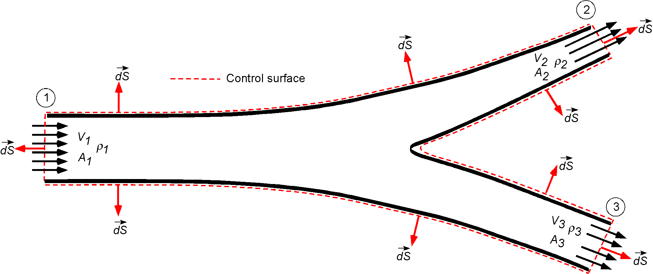
It can justifiably be assumed that hydraulic fluid is incompressible, i.e., ![]() constant. Again, at least in the first stages of analysis, it would make sense to assume that the pipe flow is uniformly axisymmetric, which would be equivalent to a one-dimensional assumption in that the flow velocities are constant over every cross-section. It is not explicitly stated that the flow is steady but based on the (limited) information given, it is probably safe to assume that it is steady.
constant. Again, at least in the first stages of analysis, it would make sense to assume that the pipe flow is uniformly axisymmetric, which would be equivalent to a one-dimensional assumption in that the flow velocities are constant over every cross-section. It is not explicitly stated that the flow is steady but based on the (limited) information given, it is probably safe to assume that it is steady.
Remember, that the first step in the analysis is to think about a sketch of the control volume and the control surface and annotate it appropriately. The governing equation in this case becomes
![Rendered by QuickLaTeX.com \[ \oiint_{S} \rho \vec{V} \cdot d\vec{S} = \oiint_{1} \rho \vec{V} \cdot d\vec{S} + \oiint_{2} \rho \vec{V} \cdot d\vec{S} + \oiint_{3} \rho\vec{V} \cdot d\vec{S} + \oiint_{\rm walls} \rho \vec{V} \cdot d\vec{S} = 0 \]](https://eaglepubs.erau.edu/app/uploads/quicklatex/quicklatex.com-05df7c42c2856ff8041deee5489007d9_l3.png)
where the mass flow over the solid walls would be zero, i.e.,
![]()
If the flow velocities are constant over their respective areas, then
![]()
and if the density is constant (which it is for a liquid) then
![]()
noting the negative sign on the first term and its significance. In general, considering the flow out of the junction as positive and the flow into the junction as negative, then for steady flow at any junction the algebraic sum of all the mass flows must be zero, i.e.
![]()
Another way of looking at the result in this case is to write
![]()
where ![]() is a volume flow rate. Of course, if there was no third exit then the problem can be reduced to the one previously considered and
is a volume flow rate. Of course, if there was no third exit then the problem can be reduced to the one previously considered and
![]()
Summary & Closure
The application of the principle of the conservation of mass to a fluid results in an equation called the continuity equation. This equation applies to all types of fluids, viscous or inviscid, compressible or incompressible, steady or unsteady, etc. In application, the continuity equation can be simplified from its most general form by making various assumptions as they may apply to the problem of interest. However, it should be remembered that all assumptions must be justified, which in some cases may not be easy to establish a priori and so caution should be used. The most common simplification is to write the continuity equation in one-dimensional form, i.e., in terms of fluid properties that change in only one direction. While the continuity equation can be useful by itself to solve certain simple classes of fluid flow problems, the solution of most real problems, however, will generally need to invoke the principles of conservation of momentum and energy to elicit the information that is needed.
- Think about a situation where the size of the control volume changes with time. What form of the continuity equation would be needed in this case?
- Think of some fluid flow problems where a Lagrangian flow model might be preferable to solve the problem.
- A good video on some basics of the continuity equation.
- Another video on the use of the continuity equation in fluid mechanics.
- To learn more about the Lagrangian and Eulerian flow models, watch this video.
martinpeireggived.blogspot.com
Source: https://eaglepubs.erau.edu/introductiontoaerospaceflightvehicles/chapter/conservation-of-mass-continuity-equation/
0 Response to "What Are All the Continuity Equations"
إرسال تعليق